Sending and receiving images over amateur radio using SSTV can be lots of fun. This short article, courtesy of Andy M6XFC, gives some information on how to get started with SSTV on a Baofeng:
SSTV on a Baofeng?
Andrew M6XFC recently passed his Foundation exam at CARS, after studying with Essex Ham’s Foundation Online course. He’s been keen to dabble in slow-scan TV after seeing a live demo on the Essex Ham table at the November Essex Skills Night.
To get started, he tried a basic test – using his Baofeng and a smartphone propped up against it. It worked, and he was able to decode the testcard / identification transmission from the Clacton SSTV repeater.
For something more efficient, he looked at knocking up a lead. He had a useless £2 delivered speaker mic for his Baofeng – which he was hoping would make the perfect donor for a cable between the radio and audio connection of a computer / smartphone. Concerned about the connections and audio levels going into the mic, he asked for some advice in our Email Discussion Group, where he got some excellent advice from Ed G8FAX. Here’s how he got on:
Designing The Solution
Ed’s first reply suggested the need to attenuate the signal coming into the mic, as follows:
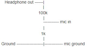
“In essence, you are correct it is an attenuator, typically a simple voltage or potential divider circuit formed by two resistors. Often used are values of 100k and 1k Ohm in series and wired across the output, with mic connection being made across the 1k resistor and ground (common).”
After some research, Andrew replied, suggesting the following:
… which Ed confirmed would likely do the job.
Making the Mic Mods
After a few weeks of silence over the Christmas Break – an update from Andrew, as follows:
“So, the build is complete, and it works!!! Not my finest soldering or craftsmanship, but it does the job and it is quite a clever design I think.”
Here’s Andrew’s summary of how this was achieved:
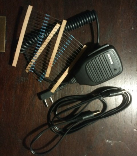
The parts:
- A £2 delivered speaker mic which claims to be BaoFeng, but really isn’t
- An old 3.5.mm audio lead from a long-defunct computer
- Some resistors (2 x 1k and 2 x 100k used)
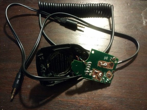
Inside the speaker mic, the circuit board was a similar footprint to the unit, and entirely covered in copper (which was then coated) with lines removed to create tracks for the ‘live’ connections, most of it was one large ground connection therefore. Inside was a surface mount mic and switch and a speaker on leads.
I exposed areas of copper by scraping with a screwdriver and isolated them from the rest of the board by scratching the copper away with a drill bit, so as to create my own copper pads. Continuity (or lack thereof) was tested with a multimeter to check there were no shorts between my new pads and each other or ground. Speaker and microphone were removed so their copper pads could be reused and holes drilled in my new pads to accept the components and jumper wires.
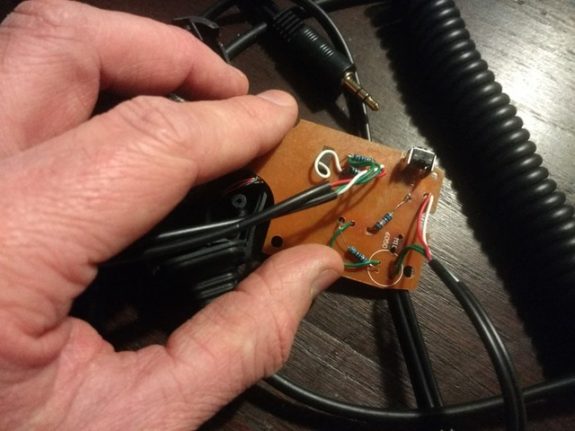
The leads and resistors were wired in according to the schematic above, thanks for which goes to Ed G8FAX, and yes the iron was too hot to start with and I did burn copper off. I think I failed to get all the green off in places as a few joints did not go so well and I am guessing were contaminated, but they work.
With the work complete, the new leads were wrapped around and tucked between the screw posts inside the case to reduce the chance of pulling on the solder joints, and it was reassembled.
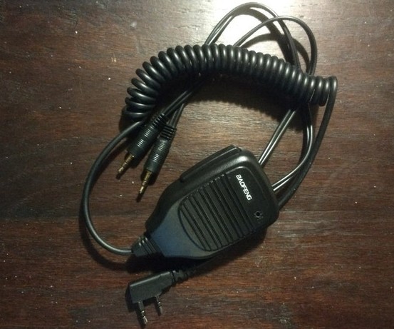
The finished article, my ‘data interface cable’ substitute with built-in PTT button. The lead to the mic connection on the computer is coming out the mic side of the housing, so as to indicate which is which (I know this is technically wrong when you think about, but it seems the more obvious way round), and it works a treat.
I am within range of MB7TV, and this is what I picked up, much better than placing a phone speaker next to the mic of the radio.

It does work the other way around as well, though that was tested with the other radio having a phone near the speaker, so the results were clearly less noteworthy, but I see no reason why it should not be just as good if the other end is better set up.
I can’t wait to get out and play.
Andrew M6XFC
Thanks to Andrew for allowing us to reproduce details from his email to our discussion group. Much appreciated.
If there’s something you’ve made that you’d like to share with the amateur radio community, please get in touch!


Well done , a great sense of achievement I bet ! And great how everyone gets together to help each other out ..it’s what it’s all about , well done everyone xx …soldering ..don’t like it ..for that alone you get a pat on the back xx
Similar to what I used when I started monitoring psk31.
Under lift conditions I can rx the Clacton repeater so will monitor next time condx are good.
Richard.
Yes, it was good fun and I am very pleased with the results. Just need to think of what try next.
PSK31, another data mode which is transmitted via audio? I am keen to try whatever I can with my BaoFeng.
Thank you for the feedback
Andrew M6XFC
Bonjour, je suis très novice en bidouille.
Malgré que ce soit bien détaillé,
Je ne comprends pas le câblage photo 1 (sur la platine de mon micro BAOFENG il y a plein de pistes.)
Je ne comprends pas le câblage photo 2 (je n’arrive pas à suivre les fils.)
C’est peut-être simple (mais trop compliqué pour moi.)
Pouvez-vous tout simplement m’expliquer plus en détail ?
Je vous remercie.
Raymond.
Here’s a quick translation of Rollet’s question:
“Hello,I am very new to homebrew.
Although there is a lot of detail, I don’t understand the cabling in photo 1 (on the circuit board of my BAOFENG microphone there are lots of tracks.)
I don’t understand the cabling in photo 2 (I can’t manage to follow the wiring.)
This is probably simple (but too complicated for me.)
Could you just explain it to me in more detail?
Many thanks.
Raymond”
If anybody wants to reply in English then I’ll have a go at translating that into French as well.
73
Edmund M0MNG
Did you try the transmit part also?
Any mods needed for that?
Hello, TX works also. Both sides have identical potential dividers. The headphone output of the computer goes through a potential divider as above and in to the microphone socket of the radio, the audio from the speaker/mic jack on the side of the radio goes through a second, identical potential divider to the mic input on the computer. I have found some mobile phones work better with a 33k ohm resistor in the potential divider between the phone’s headphone connection and radio’s microphone connection. I have also found that speaker mics with an led must be wired differently in the plug as using the lead from one of those causes the radio to re-key as soon as it de-keys from vox (or perhaps I just had a bad lead) Andrew M0ORB (previously M6XFC)