
In Introduction to HF – Part 2, we covered transceivers and offered some tips on buying your first HF radio – Now we move onto the final (and most important) part of this article (and your station): Aerials. There won’t be too much technical jargon although some new concepts (to the Foundation/Intermediate level) will arise – But, it also has lots of diagrams so everything will be explained in as much detail as possible.
Aerials
An efficient aerial can work wonders – If you’re running only 10-watts but have an efficient aerial, it might just be better than 100-watts into a poor aerial.
An aerial works best when it’s tuned to the frequency you are operating on – Whether it’s a vertical, horizontal dipole or a beam (yagi), if the size isn’t correct for the frequency, performance will be poor. A simple formula to find the wavelength of a frequency in metres is 300/freq(MHz), eg: 300/14.2 = 21.13m (hence the 20m band). Therefore, you can use 150/freq to find the overall dipole length, or 75/freq to find how long each “leg” of a dipole (or 1/4wave vertical) needs to be, eg: 75/14.2 = 5.28m. If you’re of the imperial persuasion, 468/freq(MHz) will give you the wavelength in decimal feet.
It’s true what they say: Size does matter! If the aerial is the wrong size, it won’t do what you want it do… What do we want it to do? Simple: Radiate as much of the power we put into it as possible and in the right direction/s.
In Part 1, we touched on Skip, the way in which radio waves travel – A low-angle of take-off is desired for working far-away (DX) stations but a high-angle is more useful on bands like 40m where a more local contact may be desired.
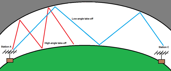
If you imagine a ball bouncing up and down, it gets progressively weaker with each bounce – This is much like how radio waves bounce off of the ionosphere. If the take-off angle is high, there will be more “bounces” required to achieve the same distance that a low-angle signal would make in only, say, 3 bounces. The signals take a long time to reach (and hopefully bounce) off the ionosphere before coming back down again.
Coax vs Balanced (ladder-line)
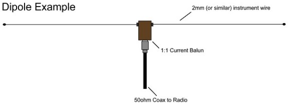
Before we get to the aerial, a few words about feeders: Coaxial cable is the easiest to work with, and even the thinner type such as RG58 can be used on HF frequencies. Coax, despite having a centre and outer, is an un-balanced feeder – But an aerial such as a dipole is balanced (ie: 2 equal sides, a symmetrical antenna). It is possible to connect your dipole directly to you coax and for everything to work just fine: If the aerial is cut for that frequency, then you’ll be able to use it without worrying about a poor SWR.
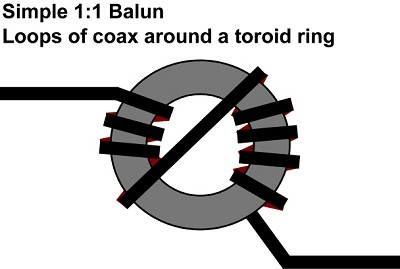
A problem that can occur with coax is what’s known as Common-Mode Currents and this is where the outer of your coax (the braid) can radiate RF and come back into you Shack – This not good! A simple cure (and good practice) is to use a balun at the feedpoint – As the name suggests, it converts a BALanced aerial to an UNbalanced feeder. It comprises a ring which is wound with several turns of coax, mounted in a box and usually has 2 screw terminals (for the aerial wires) and an SO239 connector for your coaxial-cable. RF getting into your equipment is a common problem, especially with higher power operating – The most often heard issue is RF feedback on somebody’s audio. Their audio becomes very scratchy or as soon as they talk, you’ll hear an immediate feedback loop of noise (much like feedback from a microphone near a speaker).
The balun, shown below, is a cheap and effective way of keeping the RF out of your shack and in the air:
You may have also heard of an UnUn, which is an Unbalanced to Unbalanced device, usually wound with a 9:1 ratio, these are used with end-fed (or long) wires. The theory being that the wire presents as a fairly high (around 450ohms) impedance across a range of bands, the UnUn transformer converts it down to a more “radio friendly” 50ohms (or thereabouts).
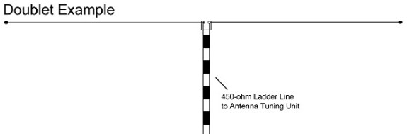
Coax can be very lossy when you are trying to use it with an aerial on a frequency that it is not resonant on, eg: a 14MHz dipole on 7MHz. However, when you use a balanced feeder like 300ohm ribbon or 450ohm ladder-line, the losses are significantly less. Many Hams use a Doublet which is simply 2 equal length wires fed with balanced-line (see Dipoles and Doublets section below). Balanced-line is very forgiving when used with a poorly-matched antenna but it does have drawbacks: Routing the cable can be tricky: Not as easy to thread through holes as coaxial cable.
You may wonder why, despite the lossy nature of using coax, that ATUs (Antenna Tuners) come with SO239 coax connectors. Simple marketing, I’m afraid. Plus, coax is seen as a simple feeder to use, is commonly available, quite cheap and companies would rather sell you a magic box of tricks for £150 than reveal that a £15 length of ladder-line would be more efficient. Of course, putting-up resonant dipoles for ALL of the HF bands isn’t something everyone can do, so compromises have to be made.
Traps and Loading Coils
Often, you can make a Dipole that’s cut for the lower HF bands work on the higher ones by adding “traps” – These are a tuned filter that prevents a particular frequency from passing but lets others through. The W3DZZ antenna is good example of this: It’s an 80m Dipole with a pair of 40m traps so that it works on 80m, 40m, 20m, 15m, and 10m. If you have around 110ft of space, that’s a very convenient aerial to have!
Loading Coils are used to physically shorten an aerial so that it may fit into a smaller area. Unfortunately, as convenient as that may be, they are generally quite lossy and should be reserved for use on 160m+80m aerials. A loading-coil can also reduce the bandwidth of an antenna, so that the length of it must be cut for the part of the band that you wish to use – If you’re doing this for a 3.5MHz dipole, the difference between the bottom-end (CW) and the top (SSB) is as much as 3-metres.
Dipoles and Doublets
Probably the most common types of antenna used on HF – A dipole is simple to equal pieces of wire at the end of a length of coaxial cable. In the case of a 20m dipole, each wire will be about 5.28m long bringing the total length to around 10.6m. Due to the relationship between certain bands, a Dipole cut for a particular band may also work on another, eg: The 15m band (21MHz) is an odd-harmonic of 7MHz, meaning that a 40m Dipole will present a reasonable match on the 15m band.
A Dipole usually offers a high take-off angle unless it can be raised to a 1/4wave above ground, eg: 5m AGL if it’s 14MHz antenna. Dipoles are usually installed flat-top, so that they are the same height at each end and in the middle – But the Inverted-V is another popular method of installing a Dipole (or Doublet). Using a single support, the feed is up high whilst the ends come down to near ground level.
A Doublet is, essentially, a Dipole but fed with a balanced-line such as 450ohm ladder-line. 66ft is a popular length, and this gets you onto 40m quite nicely as well as the higher-bands without too much compromise. The losses (due to the high SWR) on the other bands will be negligible unlike a coax-fed Dipole. See the NorCal Doublet website for information on how to build a very cheap Doublet.
Verticals
A vertical aerial is the type used for DX’ing on the lower HF bands due to its low-angle of take-off. As you saw from the diagram above, a low-angle is preferred for DX’ing. There are also a number of other factors in making a vertical efficient: Is the aerial off-ground or at ground-level? Do you have an extensive radial system? Is the aerial tuned to the frequency you are operating on? Another important factor is the local noise-level as verticals can easily pick-up local noise such as electrical interference, plasma televisions and other domestic appliances.
The vertical is usually a 1/4wave radiating section with 4x 1/4wave radials – This is the “ideal” when the antenna is in free space (ie: on top of a pole), but what if your aerial is cut for the 40m band? At 10.5m tall, ground-mounting is the most likely option for most. Luckily, when a vertical is ground-mounted the radial system can be “compromised”. This means that you can put down as much wire as you can manage, the lengths aren’t critical but if you can get them as long as 1/4wave then you’re off to a good start. Try to put down at least 20 radials – More is better. A vertical with a poor ground system will simply be central heating for the worms!
Full-Wave Loop (eg: Delta-Loop)
A popular aerial for several reasons: It can be installed around the top of your garden fence for stealth operation, they are typically low-noise antennas and, when fed with a balanced-line, can work on many HF bands with surprising results. When fed with coax they do not appear as a 50ohm load, so some form of matching is required: This can be via a 4:1 balun at the feed-point, or you can use a 1/4wave “matching-stub” of 75ohm coax (the white television sort).
Aerial Ideas
The following aerials are suggestions for those with a small garden, the inability to put something up “in the air” or those with “nosey” neighbours! There are many articles on “short antennas” although most of them are from an American perspective so their definition of a “small back yard” is about 100ft. My definition is more like 50ft…
Attic Dipole: The loft can be a great place to hide a simple dipole, especially if your Shack is in the spare room – If your loft is 6m wide, then gives you space for a dipole for 12m (24.9MHz). Of course, you could bend the wires around the sides of the loft and have a dipole for a lower band, perhaps 20m. Bending the wires around (or down) corners is perfectly acceptable – just try to do with both ends, the Dipole is a balanced antenna, remember?!
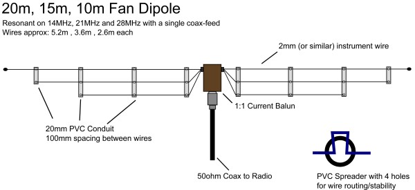
Fan Dipole: Let’s say you have room for a 20m dipole (about 10.5m), what about other bands? Did you know that you can add additional wires for, say, 15m and 10m and a 3-band antenna? With the wires spaced around 100mm apart, this simple Fan Dipole will be resonant on 14MHz, 21MHz and 28MHz and only require 1 coax feed.
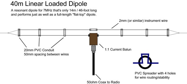
40m Linear-Loaded Dipole: This is a great aerial for use on 7MHz if you (like me) have a 50ft garden – It’s a full-length dipole but the wires are folded back to the centre making it around 60% the length of a conventional “flat-top” dipole. The wires on my own aerial are about 12m. From the formula I quoted earlier, you’ll know that each leg of a 7MHz dipole (cut for 7.1MHz) is around 10.5m, so cut your wires longer (trimming is easy, adding wire on is harder). This type of aerial is much more efficient that using loading-coils to physically shorten the aerial – Loading-coils are fairly lossy and should be avoided if possible.
Further reading on this technique is available on this page: Short Ham Antennas for HF
The diagram below shows how simple this aerial is – By using 50mm lengths of PVC Conduit, we can make a series of spreaders that the wires route through and allow them to remain parallel.
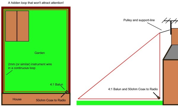
Loop: As I mentioned above, the Loop is a great stealth antenna – it can be hidden along a fence or, if you have a single vertical support, can be mounted as a Delta. Remember, a full-wave loop fed with coax does not present itself as 50ohms so don’t forget the 4:1 balun at the feed-point! Of course, you can feed it with ladder-line if you plan to use it on several HF bands. In the image below, you can see 2 examples of how such a loop might work.
The vertical loop can be fed at different positions, either for convenience or to obtain horizontal/vertical polarization (or a low/high take-off angle).
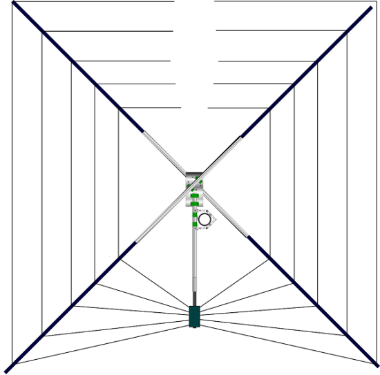
CobWebb: Named after its designed, Steve Webb, this is a compact 5-band antenna comprising 5 separate Dipoles for 14MHz, 18MHz, 21MHz, 24.9MHz and 28MHz. It looks very much like a rotary washing-line as is only 2.7m (7ft) square, an idea small-space aerial. It can be purchased as a kit but constructed using readily available parts for around £70. For information on my own CobWebb build, see my website article.
I’ve just scratched the surface of HF antennas, there are plenty of other aerial solutions which can easily be found using Google or why not ask here on the Essex Ham forum if you have a specific problem with your garden/aerial plans? If you’re keen to try something with HF, the key is to experiment – Wire isn’t too expensive so you can try out some ideas without spending too much.
Thanks to Charlie Davy, M0PZT for this excellent three-part Introduction to HF. Hopefully you’ve found it useful. If you have any questions or comments, please add them in the section below.
For more words from Charlie, and details of his amateur radio software, go to www.m0pzt.com, or follow him on Twitter @M0PZT
thanks for getting started chapters, will help with my studies for foundation licence. waiting for the areil phd. im hoping to get a GW call sign. merry christmas to all
No worries Mike. Hope it’s a help. We have plenty of other guides on here – but if there’s anything we’re missing, please let me know. 73 Pete
thanks again for starter chapters. passed my foundtion this week.
Thanks for the started guides, very helpful
Gerard
PD0GMU
Netherlands
Great article great organisation and well presented very professional
Thanks for sharing
de
YC1LBQ
Thanks for the Great Article, perfect for a new HAM such as myself.
de AC3DH
Thank you for this great material – lots to think about when getting in to HF
So, i have a 127 foot long wire attached to 49 foot of rg58 with a xiegu g90 . Now my problem is i sit in a low trough so everything seems to pass me by, my question is whats a better option? Vertical also possible annoyed neighbours by big antenna
Thanks Mike. Just lost all my antennas in recent storm up here in Eastern Scottish Borders near the coast. Having to rethink what I will now use as masts snapped. Antennas were a multi band inverted v
with 3 wires for 40, 20 and 10M at 12 metres high fixed to side of house with top just above apex and an HWEF on a 24 foot free standing mast made with plastic water pipes. Cheap but not durable. Will take some of these designs on-board and get building although replacement cheap masts are going to be a problem. Recovering from a stroke and not very mobile although radio keeps me sane. Telescopic mast that can be quickly lowered seems to be a good option but rather expensive. Pension does not stretch too far so cheaper options are the way for to go. Have managed contacts at 2000 miles with the inverted V. Cannot progress licence beyond foundation just yet because of stroke so limited to 10W. Getting out on the air just the same. Thanks for all the advice on this site. 73 to all.
Doug MM7DSA
Very useful article, thanks
I built the 40 meter linear loaded dipole- excellent antenna when it was tuned in, I will say the swr went from 2.4 when hung 6 ft of my grass in the garden to 1.6 swr at its highest when hung inthe open above my house, not hard to build at all.
Cheers Robbie mm6ixh
This is great and really interesting. Would you run the wire for a loop along the top of the garden fence or could you mount it along the inside?